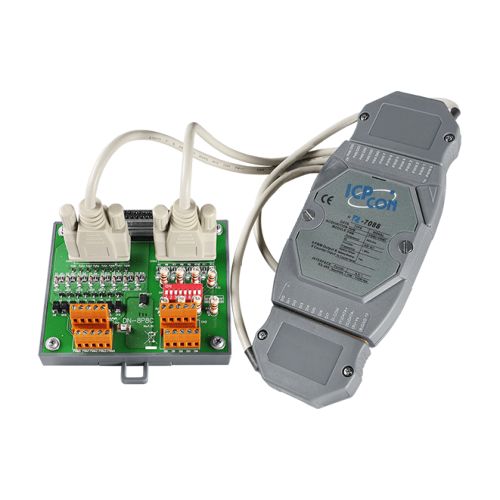
I-7088-G/S CR
8-ch PWM Output and 8-ch High-speed Counter Input Module (50 VDC) using DCON Protocol (Gray Cover) Includes DN-8P8C-CA (External Board and Cable)
The I-7088 provides 8-channel PWM (Pulse Width Modulation) Output and 8-channel Counter Input, and can be used to develop powerful and cost-effective analog control systems. PWM is a powerful technique for controlling analog circuits that uses the Digital Output to generate a waveform with a variable duty cycle and frequency which can then be used to control an analog circuit in applications such as controlling the position or speed of motors, the brightness of lamps, or the speed of fans, etc. Either burst mode or continuous mode can be used for the PWM output depending on the application. In addition, all Digital Input channels can be used as high-speed counters with a speed of up to 1 MHz. The M-7088 supports both the Modbus RTU and the DCON protocols, which can be confi gured via software, and all hardware specifi cations are the same as the I-7088. The I-7088(D)/S and M-7088(D)/S allows the load voltage to be increased from +3.5 to +50 V for the 8-channels PWM (Pulse Width Modulation) output and the 8-channels high-speed counter.
I-7088-G/S CR: I-7088 with DN-8P8C-CA External Board (Gray Cover) (RoHS)
- 8-channel PWM Output and 8-channel Counter Input
- Burst Mode and Continuous Mode for PWM Output
- Software and Hardware Trigger Mode for PWM Output
- Individual and Synchronous PWM Output
- High-speed Counters
- 4 kV ESD and EFT Protection
- Dual Watchdog
- Wide Operating Temperature Range: -25 to +75°C
Counter Input
Channels: 8
Contact: Wet
Sink/Source (NPN/PNP): Sink
On Voltage Level: +3.5 ~ +50 VDC
Off Voltage Level: +1 VDC Max.
Programmable Filter: -
Programmable Threshold Voltage: -
Counter Bits: 32-bit
Counter Mode: Up
Encoder Mode: -
Frequency Mode: -
Virtual Battery Backup: Yes
Frequency Accuracy: -
Max. Speed: 1 MHz
PWM Output
Channels: 8
Type: PWM, TTL
Sink/Source (NPN/PNP): Sink
Load Voltage: +5 ~ +50 VDC
Max. Load Current:
- Sink: +50 VDC @ 200 mA/Channel
- Source: -
PWM:
- Frequency: 1 Hz ~ 500 KHz
- Duty Cycle: 0.1 to 99.9%
- Mode: Burst, Continuous
- Burst Count: 1 to 65535
- Trigger Start: Hardware or Software
Power-on Value: -
Safe Value: -
Communication
Interface: RS-485
Bias Resistor: No (Usually supplied by the RS-485 Master. Alternatively, add a tM-SG4 or SG-785.)
Format: (N, 8, 1) (N, 8, 2) (E, 8, 1) (O, 8, 1)
Baud Rate: 1200 to 115200 bps
Protocol: DCON ; Modbus RTU, DCON
Dual Watchdog: Yes, Module (1.6 Seconds), Communication (Programmable)
LED Indicator/Display
System LED Indicator: Yes, 1 as Power/Communication Indicator
I/O LED Indicator: 7-segment
7-Segment LED Display: -
Isolation
Intra-module Isolation, Field-to-Logic: 2500 VDC
EMS Protection
ESD (IEC 61000-4-2): ±4 kV Contact for each Terminal
EFT (IEC 61000-4-4): ±4 kV for Power Line
Surge (IEC 61000-4-5): -
Power
Reverse Polarity Protection: Yes
Format: +10 ~ +30 VDC
Baud Rate: 2.9 W
Mechanical
Dimensions (L x W x H): 123 mm x 72 mm x 35 mm
Installation: DIN-Rail or Wall Mounting
Environment
Operating Temperature: -25 to +75°C
Storage Temperature: -40 to +85°C
Humidity: 10 to 95% RH, Non-condensing


