features and benefits
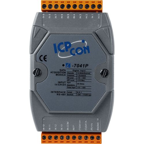
The I-7041 and I-7041P provide 14 channels for digital input, each of which features photocoupler isolation.
In addition, either sink- or source-type digital input can be selected via wire connections, and all channels are able to be used as 16-bit counters.
The I-7041D and I-7041PD include 14 LED indicators that can be used for DI channel status monitoring.
4 kV ESD protection and 3750 VDC intra-module isolation are standard.
The hardware specifications for the M-7041 and M-7041P are the same as for the I-7041 and I-7041P, and support both the Modbus RTU and DCON protocols, which can be configured via software.
ICPDAS recommends selecting the P version of the digital input module for industrial use.
- Sink- or Source-type Digital Input
- Photocoupler Isolation
- All Channels Can be Used as 16-bit Counters
- Built-in Dual Watchdog
specifications
CPU Module| Watchdog Timer | Module, Communication (Programmable) |
|---|
Isolation| Intra-module Isolation | 3750 VDC |
|---|
EMS Protection| EFT (IEC 61000-4-4) | ±2 kV for Power Line |
|---|
| ESD (IEC 61000-4-2) | ±4 kV Contact for Each Terminal | ±8 kV Air for Random Point |
|---|
LED Indicators| Status | 1 x Power and Communication |
|---|
Digital Input/Counter| Channels | 14 |
|---|
| Type | Wet Contact |
|---|
| Sink/Source (NPN/PNP) | Sink/Source |
|---|
| ON Voltage Level | +11 VDC Max. |
|---|
| OFF Voltage Level | +19 ~ +30 VDC |
|---|
| Max. Counts | 65535 (16-bit) |
|---|
| Frequency | 100 Hz |
|---|
| Min. Pulse Width | 5 ms |
|---|
| Input Impedance | 3 kΩ |
|---|
| Overvoltage Protection | ±35 VDC |
|---|
COM Ports| Ports | 1 x RS-485 |
|---|
| Baud Rate | 1200 ~ 115200 bps |
|---|
| Data Format | (N, 8, 1) |
|---|
| Protocol | DCON |
|---|
Power| Reverse Polarity Protection | Yes |
|---|
| Input Range | +10 ~ +30 VDC |
|---|
| Consumption | 0.2 W |
|---|
Mechanical| Dimensions (mm) | 72 x 123 x 35 (W x L x H) |
|---|
| Installation | DIN-Rail Mounting |
|---|
Environment| Operating Temperature | -25 ~ +75 °C |
|---|
| Storage Temperature | -40 ~ +85 °C |
|---|
| Humidity | 10 ~ 95% RH, Non-condensing |
|---|